
Before you take a deep dive into working with your Arduino its a good idea to first get a birds-eye-view of what this world called tangible is all about.
In this exploration I will introduce a general framework for thinking about and creating interactive and behavioural artworks.
One of the biggest challenges students face when entering into the world of tangible is sorting how to relate lived experiences with how a microcontroller and a circuit see the world.
It is a big conceptual leap — but the tangible matrix below will give you a point of departure for this journey.
Video :: tangible matrix overview
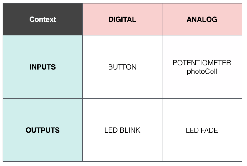
tangible matrix
As indicated in the video, there are four basic circuit patterns or interactions that we can work with microcontrollers. That’s it. Just four. Mastering these will give you a strong foundation or exploring more advanced contexts in tangible spaces.
I find it can be really helpful to start your tangible journey by thinking about how you experience the world. Two really important systems shape how you become aware of and move through the world. They are your sensory systems and the skeletal muscular system that enables movement.
Inputs
Let us begin by considering your sensory systems and let us describe those as inputs. Sensory systems — vision, hearing, taste, touch and smell — are how you bring information into your body. We also have systems that lets us evaluate our internal state — our sense of balance, proprioception (kinesthesia) or our sense of our own movements, thermoception (temperature), itch, muscle stretch and hunger. Each of these is a pathway for us to gather information about our body and how it relates to the world.
Inputs are circuits or contexts that bring information into our system.
Outputs
We can also consider the ways we move, behave and impact our environment. We will call these outputs. These may include sounds, movement, chemical signals (pheromones), sweat, exhaled breath or even waste products.
Outputs are circuits or contexts that push information out of our system.
How does an Arduino sense and affect the world?
Your Arduino (Uno, Minima, huzzah, esp32 – microcontroller) also has inputs and outputs. But it has a very constrained way of accepting information and generating actions.
In the tangible world input circuits will be broadly referred to as sensors. We will explore a number in this course, including sensors for touch, light, buttons and switches and more advanced experiences like distance ranging with sonar, and tilt and movement detection with accelerometers. You are also encouraged to find others that reach beyond our introductions.
Output circuits are also commonly called actuators or actuator circuits. These also come in many varieties. We will explore sound, light and motion as points of departure for building circuits that affect the world.
Microcontrollers primarily listen to (input) and create (output) voltages and sometimes currents. We can combine electronics (circuits) with our microcontroller to create all kinds of input and output based experiences.
Despite all of this diversity, all of thousands (millions?) of circuits that are possible — and it is amazing what is possible — ALL of the circuits fall into the matrix above: digital or analog; input or output.
Digital
Digital refers to circuits that can only be in one of two states — ON or OFF. We use some synonyms for this, we might say HIGH or LOW, or 1 and 0, or true and false, positive-voltage or ground. Think about a simple light switch in a room – it is digital and it can either be ON or OFF.
Binary (anything that has 2 parts) is the number system associated with these 1s and 0s. So digital means two states; 1,0 and is identified numerically with binary.
Binary Voltages
When we describe a digital system as being in the OFF, LOW, FALSE or 0 state, we talk about its voltage being equal to zero volts. In a circuit that means it is associated with the negative side of your battery or power supply (i will metaphorically call this the bottom of the power waterfall).
When we describe a digital system as being in the ON, HIGH, TRUE or 1 state, we talk about its voltage being equal to the positive voltage in your power supply (in an Arduino Uno/Minima this equals 5V max). In a circuit this means the part of a circuit associated with the positive side of your battery or power supply (metaphorical top of the waterfall). In this water analogy, the waterfall is either flowing or not.
Are we digital?
It is worth mentioning that the human body is an electrical system. Some events feel like they may be on/off — an adrenaline rush comes to mind — but human physiological processes tend to be exclusively analog in nature. Touch, taste, aromas, brightness, hunger, exhaustion all come in degrees.
One possible exception — resides outside the conscious range of our senses — exists at the level of individual neurons in our nervous system. Research suggests that these may be triggered in ON/OFF or digital patterns. This opens some really interesting areas of consideration. But it is worth keeping in mind that when neural activity is aggregated most actions and senses still function in analog ways.
Analog
The other kind of circuit we will encounter is analog. As we have just seen, analog circuits are much more human like.
Analog circuits refer to the worlds of continuous gradation. This could be volume of music, speed control or a motor or a light on a dimmer switch. Analog systems / circuits embody all the intermediate shades that make experiences great.
Analog Voltages
Analog circuits require a different way of thinking compared to digital systems.
Analog circuits can assume any voltage between ground (bottom of waterfall) and the system’s positive voltage (5V for Uno/Minima, top of waterfall). So we can think of analog circuits as having power waterfalls that flow at different heights.
Summary
There are only four basic contexts that we need to consider when working with microcontrollers like the Arduino Uno/Minima. Those contexts are defined by direction of electricity flow; input and output, as well as the number of voltage states a circuits can achieve; 2 for digital, infinite (from zero to +V) for analog.
The tangible matrix above summaries these contexts and offers basic examples of each context.
Explore each context in the related building blocks: